To avoid these ads, REGISTER NOW!

In-floor Scissor Lift Install

Paul Bird

Active member
Joined
Jun 1, 2006
Messages
40
I finally got fed up with the task of putting a car with 2.5" of ground clearance up on jack stands and decided to do something about it. A boat from China and three weekends worth of work and the problem is now solved. Here are some shots of how it went down:

Rented a concrete saw and jack hammer and dug a 24" deep hole:
LiftHolewithBase.jpg
Then I made wooden forms and a bunch of rebar:
LiftForm.jpg
1.6 yds of 5000 psi concrete:
LiftAfterPour.jpg
Finished concrete work:
LiftFinishedConcrete.jpg
Borrowed a fork lift:
LiftBeingInstalled.jpg
And done:
LiftFlat.jpg
Liftupalittle.jpg
Liftupahalfwayside.jpg
Liftfullheightside-1.jpg

The great thing about this lift is that it is perfectly level with the ground when down so it is 100% out of the way when not in use (98% of the time). It also lifts to 73" so I can easily walk under the car when up. I am going to put down porcelain tile this weekend and then get back to work on the important stuff - like finishing my race car.
 
Last edited:
To avoid these ads, REGISTER NOW!

theroyz71

Well-known member
Joined
Apr 24, 2009
Messages
367
Location
Tennessee
Nice but do you really need that much lift? Seems a little overkill. Of course, that may be the whole point.
 
OP
P

Paul Bird

Active member
Joined
Jun 1, 2006
Messages
40
nice job! what brand is this scissor lift?
I got it direct from Ever Eternal in China. The closest thing to this I could find in the US was the single cross Bend Pak. I greatly prefer this style as it only interupts the floor directly under the platform. Plus this lift was 40% the cost of the Bend Pak which was probably made in the same plant in China.
How'd you get the PVC pipe from the wall to the pit?
I simply drove a scrap piece of 2" PVC with a sledge hammer. Every 6 inches or so I pulled it out and emptied the dirt in the pipe. It took about 15 minutes to drive it 7 feet. I thought this was going to be a major task. It ended up being one of the easiest.
Nice but do you really need that much lift?
In what respect? Height? - I am 72" tall so I wanted it to lift 72". Why would I want it to lift less than that?
 

bmwpower

Super Moderator
Staff member
Joined
Apr 24, 2005
Messages
12,578
Location
NJ
Nice job. Good alternative to a regular lift.

Am I seeing this right?? 2 teeth x 2 per side?

liftfullheightside-12.JPG
 

Quiksilver

Well-known member
Joined
Jun 22, 2006
Messages
333
Location
Loveland, OH
Awesome. great execution. Can you tell me what company you bought the lift from? I did a search, but the website that came up was written in Chinese. Thanks.
 
OP
P

Paul Bird

Active member
Joined
Jun 1, 2006
Messages
40
Am I seeing this right?? 2 teeth x 2 per side?
Yes, this is correct 2 per side per lift - 4 total engaged teeth per lift side. And it is hard to tell but they are huge and made from 3/4" thick steel. BTW, the pivots on this thing are made from 1.375" thick steel. Up close it looks like something Komatsu would make.

Can you tell me what company you bought the lift from?
http://www.ever-eternal.com/en/

I'll post pics of the inside of the control box tomorrow.
 

bmwpower

Super Moderator
Staff member
Joined
Apr 24, 2005
Messages
12,578
Location
NJ
Yes, this is correct 2 per side per lift - 4 total engaged teeth per lift side. And it is hard to tell but they are huge and made from 3/4" thick steel. BTW, the pivots on this thing are made from 1.375" thick steel. Up close it looks like something Komatsu would make.

Damn. Yea, it is hard to tell from the picts. I would like to see more teeth, but I usually overdo things and I doubt those teeth would sheer off.

Out of all the offshore lifts I've seen, that looks pretty beefy and nicely welded.
 

paranoid56

Well-known member
Joined
Dec 18, 2008
Messages
1,596
Location
San Diego, Ca
Yes, this is correct 2 per side per lift - 4 total engaged teeth per lift side. And it is hard to tell but they are huge and made from 3/4" thick steel. BTW, the pivots on this thing are made from 1.375" thick steel. Up close it looks like something Komatsu would make.


http://www.ever-eternal.com/en/

I'll post pics of the inside of the control box tomorrow.

how much did you pay? i didnt see any prices on tehre site.
Thanks
Shane
 

Torque1st

MEMBER EMERITUS
Joined
Sep 14, 2008
Messages
5,668
Location
KC Metro, Kansas
Very nice job, and a nice lift. Enjoy!

Could those scissor members be made out of rectangular tubing?
 
Last edited:

e-tek

Well-known member
Joined
Dec 19, 2007
Messages
10,690
Location
Saskatoon, SK
Wow - the install job is really well executed. This is the best alternative - maybe a better alternative to a 4-pos- I'v ever seen. Takes up NO room. Lifts to full heights. Lifts wheels clear. Easy to navigate onto. I can imagine witha little selling this taking over for 4-posts and any scizzor jacks out there. Can we see a pic of your car on it?

This is one of the few times I'd have to agree with BM though - I'd like to see a few more teeth on that locking mechanism as well. Is that the only holding device?
 
Last edited:
OP
P

Paul Bird

Active member
Joined
Jun 1, 2006
Messages
40
how much did you pay?
$1,830 + shipping. A friend got one as well so we saved a bunch on shipping them together. Total shipping was $345 each from China to Memphis. We drove 5 hours to Memphis to get them as it was going to be another $250 each to ship from there.

Two years ago I contacted EE directly and got a quote for $1500. This January I made another price request through Alibaba which sent me to EE. This time the quote was $1830. I don't know if this was an Alibaba markup or just a price increase.

Can we see a pic of your car on it?
Not yet. I am going to be putting down a through color porcelain tile this weekend (hopefully). So I don't want anything in the garage to get oil/dirt/etc. on the now clean floor.

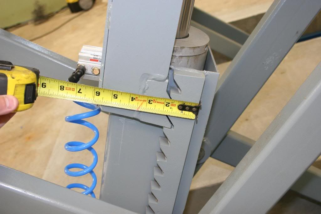
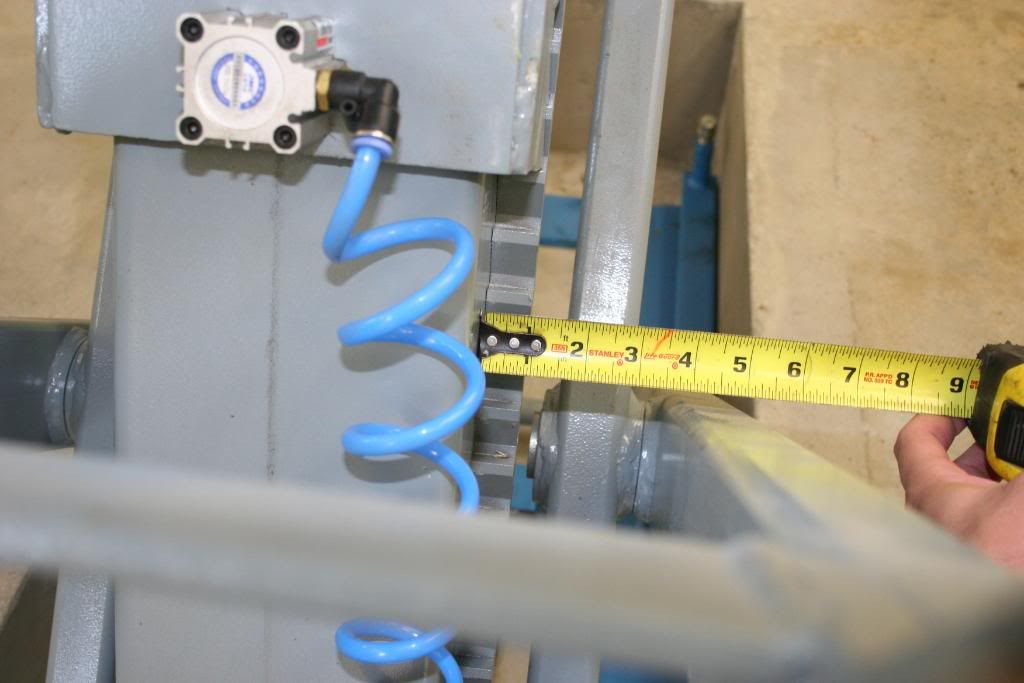
On the issue of the locking mechanism, you will see below some closeup shots of it. I too am one to quickly over build when it comes to stuff like this. Seeing it in person I can tell you that I am 100% confident that it is designed to double the rated capacity of the lift (3,000 kg). Without cutting the thing up I can't say for sure on the welds, but I don't see any 'misses' or poor penetration. BTW, they had to have some SERIOUS welding equipment to the the material thickness.

Here are some more pics:

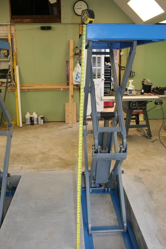
Someone emailed me that I was wrong about the max lift height even though I measured it. WTF??? Anyway, here is proof.
Liftfullheightback.jpg

Closeups of the teeth and pivots:
LiftLockingTeethSide.jpg

LiftLockingTeethFront.jpg

LiftUpperHingThickness.jpg

LiftDrivePin.jpg

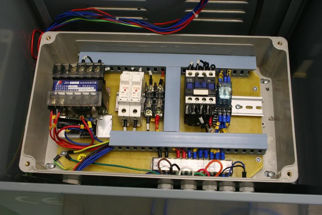
And here are some shots of the control box:
LiftControlBox.jpg

LiftControlBoxBack.jpg

LiftControlBoxInside-1.jpg

LiftControlBoxCircuit-1.jpg
 
To avoid these ads, REGISTER NOW!

Mike in Ohio

Well-known member
Joined
Sep 27, 2008
Messages
2,400
Location
Canton,Ohio
Great setup I'm wondering on price too as I didn't see anything on their website about it. Also wondering can you lift just one side at a time for a motorcycle or 4 wheeler? Mike
 
OP
P

Paul Bird

Active member
Joined
Jun 1, 2006
Messages
40
Also wondering can you lift just one side at a time for a motorcycle or 4 wheeler? Mike
No, both lifts are synchronized. Fluid from the backside of the piston on the main drive the piston on the slave.
Any reason you didn't cut 2 small holes instead of 1 big one and then have to concrete in the middle??
My friend Gene Young (who bought the other one that shipped with mine) is installing his this way. We are pouring his this Saturday and I am sure he will post pictures to this thread when done. On mine, if you look closely on my floor you can see the ends of a crack that ran right along the edge of the center section of concrete. If I had cut two holes I think that a big chunk of concrete would have cracked off and made the middle a mess.

BTW, cutting my floor out was a major pain in the ***. The concrete was 50 years old and varied from 6.5-8" thick. The saw I rented only cut down to 4.5". The rest I had to break out with a jack hammer. Getting the hole cut and broken up took over 5 hours of serious work. Gene's floor was much newer and 4.5" thick. It only took about an hour do cut his concrete up and haul it off.
 

JohnK007

Well-known member
Joined
Sep 13, 2007
Messages
807
Location
Downers Grove, IL
Very well thought out and professional looking installation Paul! You've got me thinking about possibly copying your set up when it's time to take the plunge for a lift. Don't quit the forum, I'm sure I'll be asking lots of questions when my turn comes!
 

Shocker

Well-known member
Joined
Nov 23, 2008
Messages
2,012
Location
Olympia, WA
I simply drove a scrap piece of 2" PVC with a sledge hammer. Every 6 inches or so I pulled it out and emptied the dirt in the pipe. It took about 15 minutes to drive it 7 feet. I thought this was going to be a major task. It ended up being one of the easiest.

Ok, so you just took some 2" PVC and pounded it through 50 year old concrete?

Did I miss something, because that seems like quite a feat. I would think that the PVC would shatter. Can you give me some more details.

I really like that install.

Thanks
 

wantedabiggergarage

Member Emeritus
Joined
Feb 25, 2006
Messages
3,897
Location
Independence, MO, USA.
Ok, so you just took some 2" PVC and pounded it through 50 year old concrete?

Did I miss something, because that seems like quite a feat. I would think that the PVC would shatter. Can you give me some more details.

I really like that install.

Thanks


Look at the prepour pic. I believe he pounded it through dirt, before pouring the concrete.
 
OP
P

Paul Bird

Active member
Joined
Jun 1, 2006
Messages
40
Ok, so you just took some 2" PVC and pounded it through 50 year old concrete?

Did I miss something, because that seems like quite a feat. I would think that the PVC would shatter. Can you give me some more details.
No, the PVC runs right under the concrete in dirt. I started the hole with a 2 foot long piece of 2" PVC. I did this so that I could have clearance for the sledge hammer throws and so that the pipe would not bend when smacked by the hammer. I drove this pipe in parallel to the slab about 6" then pulled it out and emptied the dirt out of the pipe. It then went back in and got driven 6" more inches. once it was 20" or so in I removed it and stared with a 4 foot section of pipe, again driving it 6 inches at a time. Once that was done, and 8 footer was driven in. I had to go 78" total from the edge of the large opening which took about 15 to 20 minutes.

I then used a laser (vertical and horizontal lines) to give me a point directly above the pipe. I measured in the 78" and drilled a series of 1" holes with a big hammer drill. I then chiseled out a 6" circle in the concrete to put an elbow and vertical run of pipe. When the concrete came for the big hole, I took the shovel and filled in the hole around the pipe and screed it off. After cure, the excess pipe at both ends of the hole were trimmed flush with the concrete.

The PVC pipe that runs between the two rectangular openings was run between the two wooden forms prior to pouring the cement.
 

Torque1st

MEMBER EMERITUS
Joined
Sep 14, 2008
Messages
5,668
Location
KC Metro, Kansas
Those scissor arms are tubing, not solid. That is the reason there are side plates and bosses welded to them. You can see the open ends and the inserts at the hinges. I have designed a lot of equipment with similar construction.
 

paranoid56

Well-known member
Joined
Dec 18, 2008
Messages
1,596
Location
San Diego, Ca
Damn. Yea, it is hard to tell from the picts. I would like to see more teeth, but I usually overdo things and I doubt those teeth would sheer off.

Out of all the offshore lifts I've seen, that looks pretty beefy and nicely welded.

Wow - the install job is really well executed. This is the best alternative - maybe a better alternative to a 4-pos- I'v ever seen. Takes up NO room. Lifts to full heights. Lifts wheels clear. Easy to navigate onto. I can imagine witha little selling this taking over for 4-posts and any scizzor jacks out there. Can we see a pic of your car on it?

This is one of the few times I'd have to agree with BM though - I'd like to see a few more teeth on that locking mechanism as well. Is that the only holding device?


why? on my fullsize 9k bendwill lift there is only two teeth on once pole and thats it. almost all full size lifts out there dont even have that many teeth. this thing looks like total over kill :D which i like.
 

chromeyellow

Active member
Joined
Apr 24, 2009
Messages
31
Location
Augusta, GA
Hey Paul, love the car build. I've been following it for what seems like forever now. One question on the lift, are there any problems with using a flat piece of metal and pushing up under the car like that? I think of things like seams and the ever popular mustang sub-frame connectors getting pinched.
 

gsport

Well-known member
Joined
Mar 1, 2008
Messages
2,176
Location
Salem Oregon
i like it too.... except i was thinking how hard it would be to get the lift out of the hole if it were to malfunction in the down position..... still way cool install
 

Torque1st

MEMBER EMERITUS
Joined
Sep 14, 2008
Messages
5,668
Location
KC Metro, Kansas
I will be using a similar pit lift in my garage without the flush mount because it is on a structural slab. There are rubber blocks that come with most of these units that deal with the seams and other points.

The quick lube places use these pit lifts in their operations for tire rotations etc. A pit lift does not lift as far as this unit does.
 
Last edited:

2WYKD

Well-known member
Joined
Apr 28, 2009
Messages
57
Location
Daphne, AL
you're my hero. this would be perfect in our motorcycle shop. you have inspired me sir...it won't be today, it won't be tomorrow, or this decade...but it will become my reality
 
OP
P

Paul Bird

Active member
Joined
Jun 1, 2006
Messages
40
One question on the lift, are there any problems with using a flat piece of metal and pushing up under the car like that? I think of things like seams and the ever popular mustang sub-frame connectors getting pinched.
The lift comes with four big hard rubber lifting blocks which I can set on the platforms under the subframes. I don't see any risk in this as that is where I jack the car up from as it is. I will likely attach some small, thin (1" square x .25" thick) rubber blocks to the car either on the subframe connectors or rocker panels to make this more convenient. Once nice thing about a 2300 lb. car is that the loads at any given point are pretty manageable.

except i was thinking how hard it would be to get the lift out of the hole if it were to malfunction in the down position
The lift halves are very heavy - about 800 lbs. We were able to borrow a small fork lift to move the lift in which made it pretty easy. Plan B was to use one engine lift on each end and roll it in. This I am glad we didn't have to do.

One challenge with this type of install is getting it out if it fails when down. I guess I would have to drill holes in or weld on the decks to be able to get something on it to pull them up enough to get started taking them out.

you're my hero. this would be perfect in our motorcycle shop. you have inspired me sir...it won't be today, it won't be tomorrow, or this decade...but it will become my reality
There are a bunch of uses for this setup beyond lifting the car. With 4x8 sheet of mdf setting across both sections it will make a killer composite layup table that is infinitely height adjustable. Just think of them as 6500 lb. capacity adjustable height saw horses.

I will also use it as a welding table and a lawnmower lift. I am going to be mounting electrical outlets on the front face of the lift sections for tools and lights. I may also put on a 2" square receiver flush in the back of each to mount a vice, shrinker/stretcher, etc. Ahhhh the possibilities.

I'll post updates to this thread when I do these things if people are interested.
 

HIRISC

Well-known member
Joined
Jun 9, 2006
Messages
828
Location
Minneapolis, MN
Very, very slick install.

That's about the best I've seen it done and I've seen a lot of in-ground installs. Makes me want to get the concrete saw out for my scissor, but I still like to move it around the garage from time to time.

Thanks for the excellent post/pics.
 

e-tek

Well-known member
Joined
Dec 19, 2007
Messages
10,690
Location
Saskatoon, SK
Paul,

All kidding aside, I have some serious inquiries after looking (and drooling of course!) over your Mustang CF project. I'm asking them here as I didn't think I should register there just for a few questions - hope that's OK with everyone. Feel free to answer any or none.... Also, I thought about PMing you the questions but I'd guess inquiring minds would also want to know!

As a preface - I built a decent IP-2 car to race a few years back and was interested in weight-saving. I want to build another as my next project and your build sure tweaked my interest!

First off, as has been said inumerable times on that thread, way cool efforts to sa the least. You are obviously one talented, smart and hard-working guy!

Next, although I read most of that thread, I didn't see anyone ask what you do for a living. By that I mean are you into CF work, or did you learn it as a "hobby"? If as a hobby, did you research it off the net, know someone who does it, or what?
Have you raced in the series you are building the car for before - or are you building it for your shot at the "big time", so to speak?
How much do you estimate the car will cost to build? Do you have sponsors, or are you footing the bill yourself? Obviously your labour could be factored in, but I just mean material, parts and tool costs...I built mine with (mostly) sponsor money and would want to share the cost of my next one too!
Are you racing now in another series?
Would you expect to be competitve in the series? (I know myself that I (or Mrs. E-tek who was the driver of my first effort) would have to be racing a season or two before and while building my next effort just to be compettive in the series the new car would be in).

Again, love the effort on both the car and the lift! And thanks for sharing it with us.
 
OP
P

Paul Bird

Active member
Joined
Jun 1, 2006
Messages
40
Thanks for the kind words. I'll try to do this as short as possible as to not totally hi-jack the thread:
This is a 100% hobby for me and I am self taught in composites, welding, electronics, suspension, tuning, and aero. I own an insurance agency. My major in college was computer science and math.

As for the car, I have and am building it completely myself which saves a LOT on the cost. Composite bodywork does not cost as much as you might think. For example, a hood mold cost me $200 to make and the hood $400. Now I can make all the hoods I want for $400 + 6 hours of time. So right now I have roughly $2,500 in bodywork and another $1,000 or so in molds. The expensive stuff is the electronics (Motec, AIM, mil-spec connectors), turbos (Garrett GTBB), transmission (Jerico WC4-4), oil system (dry sump), and motor build (VTEngines shortblock which I then assembled). But even then it is not that expensive when you do it all yourself. The downside is that it has been a six year plus project but I did squeeze in three kids during that time.

This car damn better be competitive and with over 600 rwhp and 2300 lbs. and gobs of downforce it will be. The driver I hope is. I will be disappointed with times worse than the front third of the Speed World Challenge grid. I will be pleased if I am faster than the SWC pole times.
 
To avoid these ads, REGISTER NOW!
Top Bottom