To avoid these ads, REGISTER NOW!

MP&C Shop Projects

MP&C

Well-known member
Joined
Oct 21, 2009
Messages
4,389
Location
Leonardtown, MD
This thread, while it may show quite a bit of work on vehicles that come in the shop, is primarily going to focus on providing metalworking/metal shaping tutorials, where ever possible using simple hand tools, in hopes that it may inspire others to learn the craft. While I am no expert, in many cases learning as I go, feedback and suggestions from others is more than welcome. Where I strive to improve methods with each lessons learned, outside suggestion is often the source to provoke such thought and vision. Many times this "re-thinking the process" comes via someone questioning that process shown, so feel free to ask away!


I've been travelling quite a bit for the day job all this past fall, which has put a cramp in time available in the shop, but that has subsided a bit so now is as good a time as any to start a shop thread..

This is a customer car, the owner and I discussed shaving the fender seams quite a while back, and she asked about it again last week, so I guess we're on the hook..


Picture038-1.jpg


The bolting plates are cut out of the way, and the folded flange is trimmed, leaving a bit of extra to allow for fine tuning the weld joint.


Picture039-1.jpg


Picture040-1.jpg


Picture044-1.jpg


Bottom of the fender is cut loose from the bolting plate using the cutoff wheel. Then sanding the face of the fender leaves a contrast at the bend of the flange for a good guide for trimming with snips....


Picture045-1.jpg


Picture046-1.jpg


Picture049-1.jpg


Planishing out the fold to fill the gap....


Picture050-1.jpg


Picture051-1.jpg


Clamps used to test fit. Still needs some fine tuning for zero gaps, but we'll finish that another day..


Picture052-1.jpg


Picture053-1.jpg


Picture054-1.jpg
 
Last edited:
To avoid these ads, REGISTER NOW!
OP
M

MP&C

Well-known member
Joined
Oct 21, 2009
Messages
4,389
Location
Leonardtown, MD
Thanks for the comments guys!

Got to trimming today, little to no gaps....


Picture055-1.jpg


Used the new ER70S-7 wire. Looks to me like it lays out a bit flatter...


Picture057-1.jpg


Picture058-1.jpg


Used the crowned hammer to planish the welds. This stuff appears to planish out a bit easier as well.


Picture059-1.jpg


After planishing, 1/16" wide cutoff wheel used perpendicular to the weld for grinding the welds with minimal contact patch and less heat buildup. Ground welds just proud of the metal surface, front and back, to make room for planishing the next set of weld dots. Then rather than weld the next dots in the middle, I overlapped each of the previous welds to help eliminate missed spots and pinholes. Weld, planish, grind, repeat.


Picture061-1.jpg


Picture062-1.jpg


Picture063-1.jpg


Then I got on a roll and missed some in process pics, but here is the result after dressing out all the welds...


Picture064-1.jpg


Back side....


Picture066-1.jpg


Picture067-1.jpg


Yeah, I like this much better....


Picture068-1.jpg


Picture069-1.jpg


Picture070-1.jpg
 
Last edited by a moderator:

socapots

Well-known member
Joined
Jan 3, 2011
Messages
544
Location
Canada
man your skill and attention to detail never ceases to amaze me.
i gotta learn from your threads. lol.
 
OP
M

MP&C

Well-known member
Joined
Oct 21, 2009
Messages
4,389
Location
Leonardtown, MD
Welds on the back side of the panels will get dressed just like the front side, and then sealed with epoxy primer.
 
OP
M

MP&C

Well-known member
Joined
Oct 21, 2009
Messages
4,389
Location
Leonardtown, MD
Haha! That would be a heck of a commute, either way!

About a month and a half ago a buddy of mine came over with a bumper filler panel off a 61 Starliner he's putting together as a 70th b-day present for his dad. He was using my media blast cabinet to clean off the paint and was planning on spraying some Krylon and reinstalling. Well, I had him strip the paint, I smoothed out some dings with the hammer and dolly, and here's how I finished it, using some of my Imron rather than his Krylon...


Picture%20059.jpg


Picture%20060.jpg


Well I stopped by to check it out after he installed it, and noticed the valve covers looked like someone had changed out the intake and dropped it a few times on the valve covers. So he dropped them off for some dent repair this evening...


Picture145-3.jpg


Picture146-3.jpg


Picture147-3.jpg


Picture148-3.jpg


All of these tools were used this evening at one point or another...


Picture157-2.jpg


Picture158-2.jpg


Dents were worked with various implements of destruction, filed to find the high spots, and low spots bumped up, then repeat.


Picture153-2.jpg


Picture154-2.jpg


As they will be painted, we'll leave off with the following.... Sandblasting and some H/K epoxy primer will take care of any remaining defects...


Picture155-2.jpg


Picture156-2.jpg


Picture149-3.jpg


Picture150-2.jpg


Picture151-2.jpg


Picture152-2.jpg
 
Last edited:

don long

Well-known member
Joined
Mar 31, 2012
Messages
8,840
Location
southern california
I like what I see
Nice work with a few special tools
I'm an old body man but never did the custom work
so I'm very interested in seeing how the metal guys do it

Thanks MP&C
Don

PS: I subscribed
 
To avoid these ads, REGISTER NOW!
OP
M

MP&C

Well-known member
Joined
Oct 21, 2009
Messages
4,389
Location
Leonardtown, MD
Thanks Claude & Bam....you guys do some pretty damn nice work yourselves..


One more piece to finish up the shave, the inner flange for the grille opening needed connecting together after trimming the bolting flanges.


Picture081-1.jpg


Trimmed and holes drilled for plug welds....


Picture083-1.jpg


Picture084-1.jpg


Picture085-1.jpg


All welded and dressed out....


Picture087-1.jpg


Picture088-1.jpg


As tomorrow is supposed to warm up a bit, I'm going to try and spray some epoxy primer to get the valve covers ready for the gold paint. Here they are all sandblasted, hot tanked, and ready to go....


Picture159-2.jpg


Picture160-2.jpg
 
Last edited:
OP
M

MP&C

Well-known member
Joined
Oct 21, 2009
Messages
4,389
Location
Leonardtown, MD
Here's the official 2 x 8 valve cover paint fixtures...


Picture161-2.jpg


Picture162-2.jpg


A couple coats of H/K epoxy and a guide coat and we'll let it sit a couple days....


Picture164-2.jpg


Picture165-2.jpg


Picture166-2.jpg
 

Kevin54

MEMBER EMERITUS
Joined
Jan 12, 2005
Messages
29,341
Location
Urbana, Ohio
Picture077-1.jpg

That really cleaned up the looks of the fender. Just think how many out there have just bondo'ed the seam and sanded smooth. It's great to see a "real" metal finisher. Looking forward to seeing this thread grow!!! :thumbup:
 
OP
M

MP&C

Well-known member
Joined
Oct 21, 2009
Messages
4,389
Location
Leonardtown, MD
Thanks Kevin!

I was going to start the shave on the driver's side, but a few stumbling blocks along the way...

Mocked up all the front sheet metal just to see it together again.. Gotta love that hood bird..


Picture089-1.jpg


Here's the factory seam to compare to the shaved version...


Picture090-1.jpg


Picture091-1.jpg


Bumper filler panel had been tweaked at some point in the past 50 years, so let's see what we can do to straighten it out some....


Picture092-1.jpg


Picture094-1.jpg


Used a combination of the flat and crowned body hammers, the donut dolly, the 5" dia shot bag, and a round hunk of steel.


Picture097-1.jpg


Much better...


Picture096-1.jpg


Next on the list before the next shave, a bit more rust to attend to...


Picture098-1.jpg


Used a wide sweeping radius on the cut to minimize any extra shrinking that occurs inside tight corners.


Picture099-1.jpg


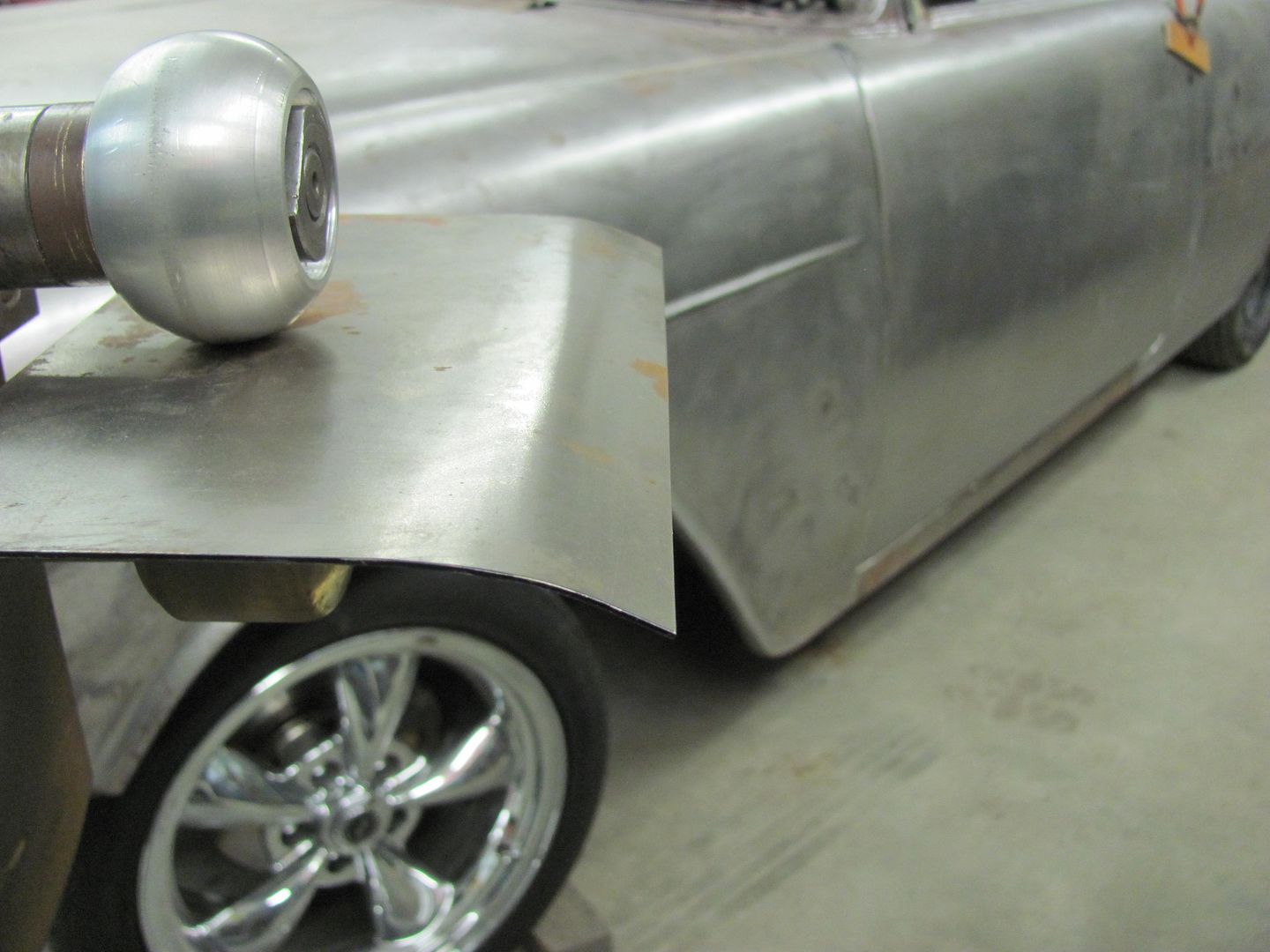
To get a good, consistent profile on the patch, I used the go kart wheel...


Picture100-1.jpg


Picture101-1.jpg


Picture102-1.jpg


Picture103-1.jpg


Laying out the pattern..


Picture104-1.jpg


Picture105-1.jpg


Picture106-1.jpg


One last test fit before tipping the flange...


Picture108-1.jpg


Dumb mistake number one....don't cut the patch so small you can't get leverage to force the flange to tip...


Picture110-1.jpg


Well, we do have a good crease to work from now. Some hammering on the 2" round anvil will work


Picture114-1.jpg


Trimmed to fit...


Picture115-1.jpg


Welded and dressed...


Picture116-1.jpg


Hey...the light even fits


Picture117-1.jpg
 

e-tek

Well-known member
Joined
Dec 19, 2007
Messages
10,690
Location
Saskatoon, SK
More great metalwork! Can I suggest/ask that you show us some of the actual bumping/shaping process? It was great to see exactly which tools you used, but would also be cool to see how you did it - I for one would like to learn how someone with your skills would tackle it.

Also, where do you buy your bead rollers? I'm looking for some different shaping wheels.

Whenever I see your metal bench in the background I think of how mine was the same - until I decided to make some room on top!

Picture114-1.jpg
 
Last edited:
OP
M

MP&C

Well-known member
Joined
Oct 21, 2009
Messages
4,389
Location
Leonardtown, MD
Whenever I see your metal bench in the background I think of how mine was the same - until I decided to make some room on top!

Hey....... it gets cleaned up once a year, need it or not.... :lol_hitti

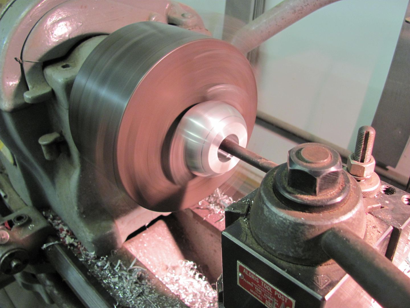
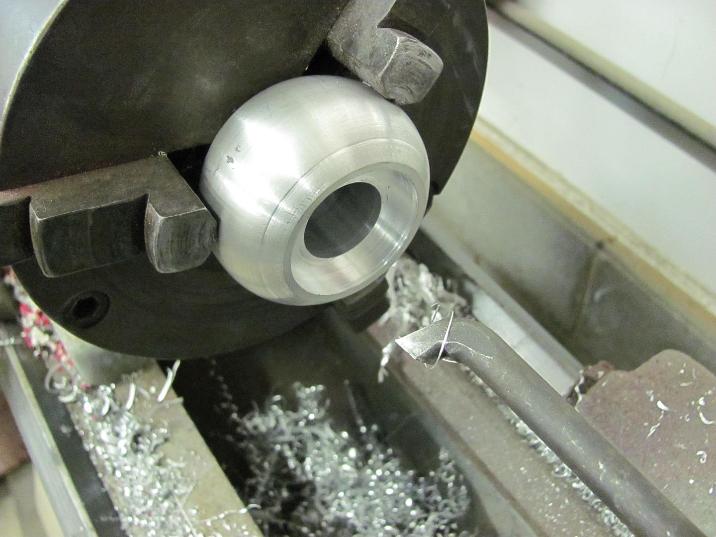
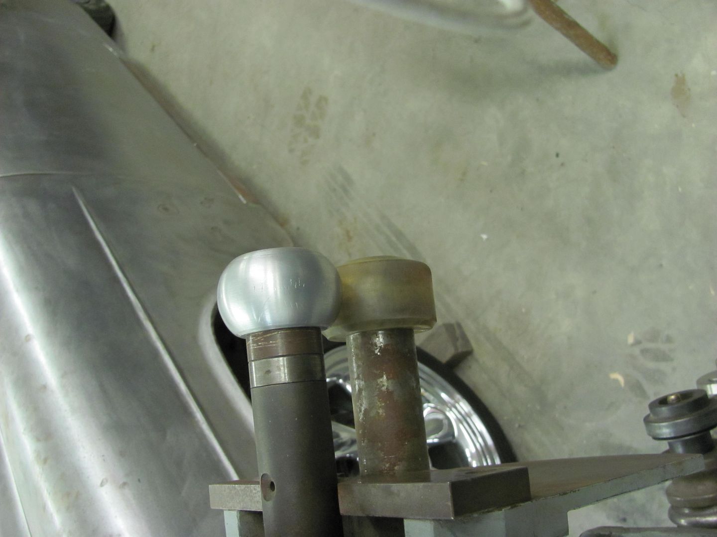
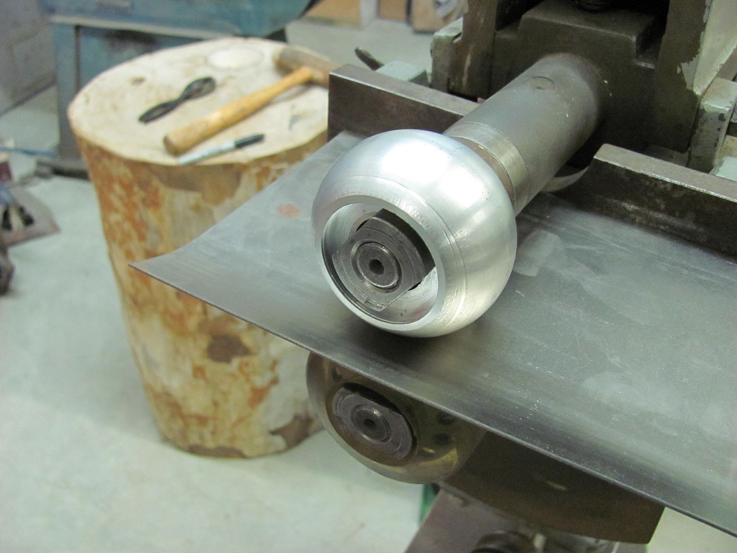
The wheels for the bead roller for the most part came with it, other than the skateboard wheels and radius roller I've added... see here


The last time I used the bead roller I made a dash insert for a Studebaker truck. It had a considerable roll added to it, which was much too tight a radius for using the go kart slick on the wheel.. This was done using the skateboard wheel and a 1/2" wide bead roller

Picture005.jpg


Picture021.jpg


Picture025.jpg


But this seemed to leave pronounced creases from the beading die, and I wanted to replace this with one with a wider radius.

Picture061-1.jpg


and a relief cut for the shaft nut...

Picture063.jpg


Picture064.jpg


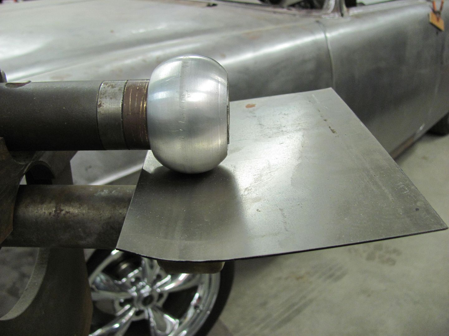
A few passes with some 18 ga......

Picture065.jpg


Picture067-1.jpg


Picture066-1.jpg


Outside has less noticeable marking.. Yeah, this should work!


With the metal bumping, a lot of times it is hard to show a tech thread on the subject because nothing is a hard and fast rule, and depending on how the panel reacts in some cases dictates a different method based on that result. But the donut dolly is discussed in pretty good detail here...


One of the guys over on the metal shaping web sites has a neat tool he sells called a donut dolly. It works more proficiently in off-dolly shrinking a crowned panel because it supports the bottom side in more than one spot (around the perimeter) as the panel is bumped from the top in the center of the donut dolly. This would seem to be useful in body repair, especially to address high spots found after blocking primer where heat would not be as feasible.

A few days ago, someone on another forum asked for advice in removing an outward roof dent. I suggested a low-buck alternative to the donut dolly, simply using a PVC pipe fitting. Where it may not work as aggressively as the donut dolly which has more mass, sometimes slower is better, especially when trying something new. I just today got around to trying this process in the shop, and rather than use the roof of something sitting here, we will use a piece of 18 ga CRS to simulate a roof.

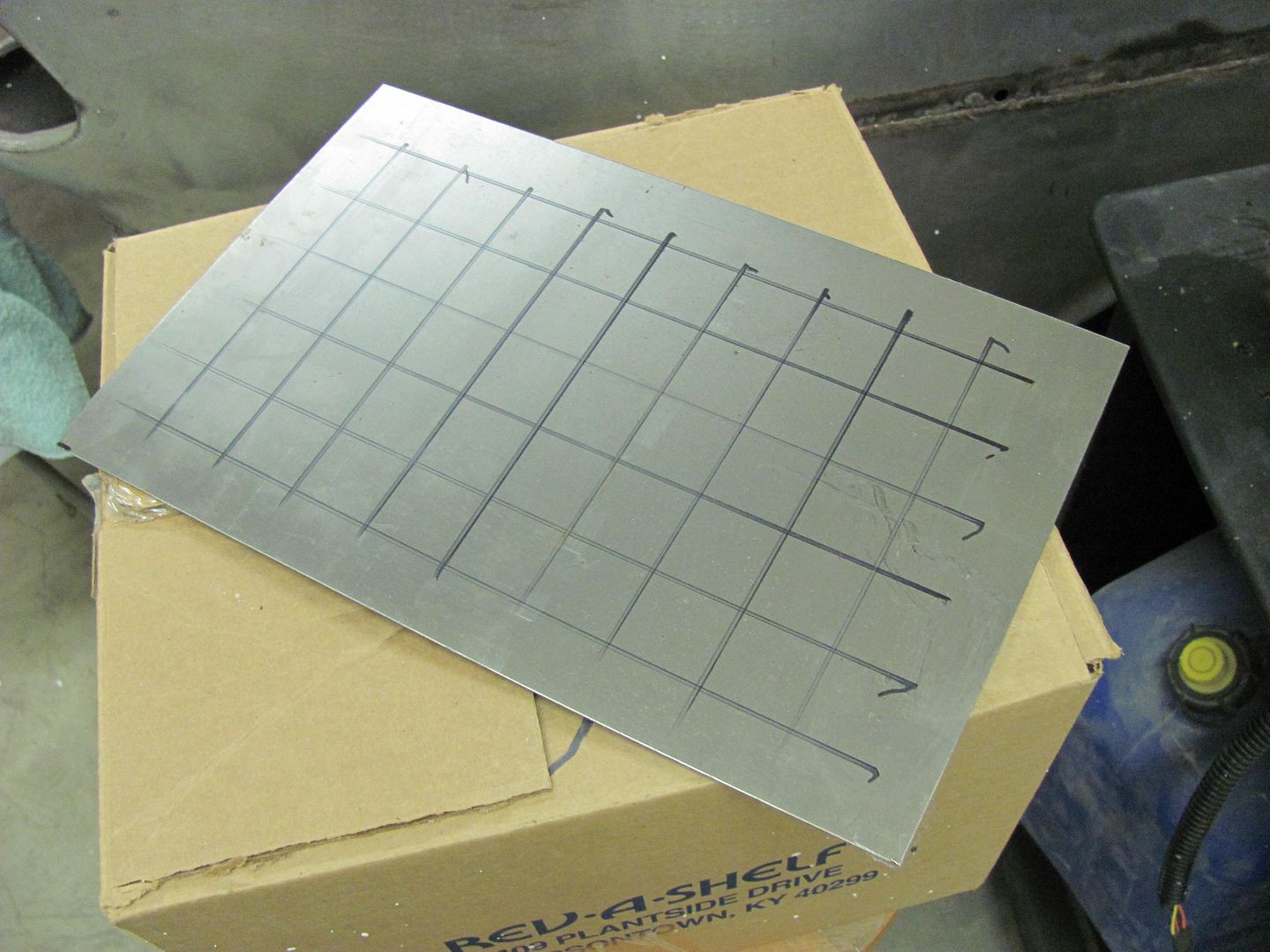
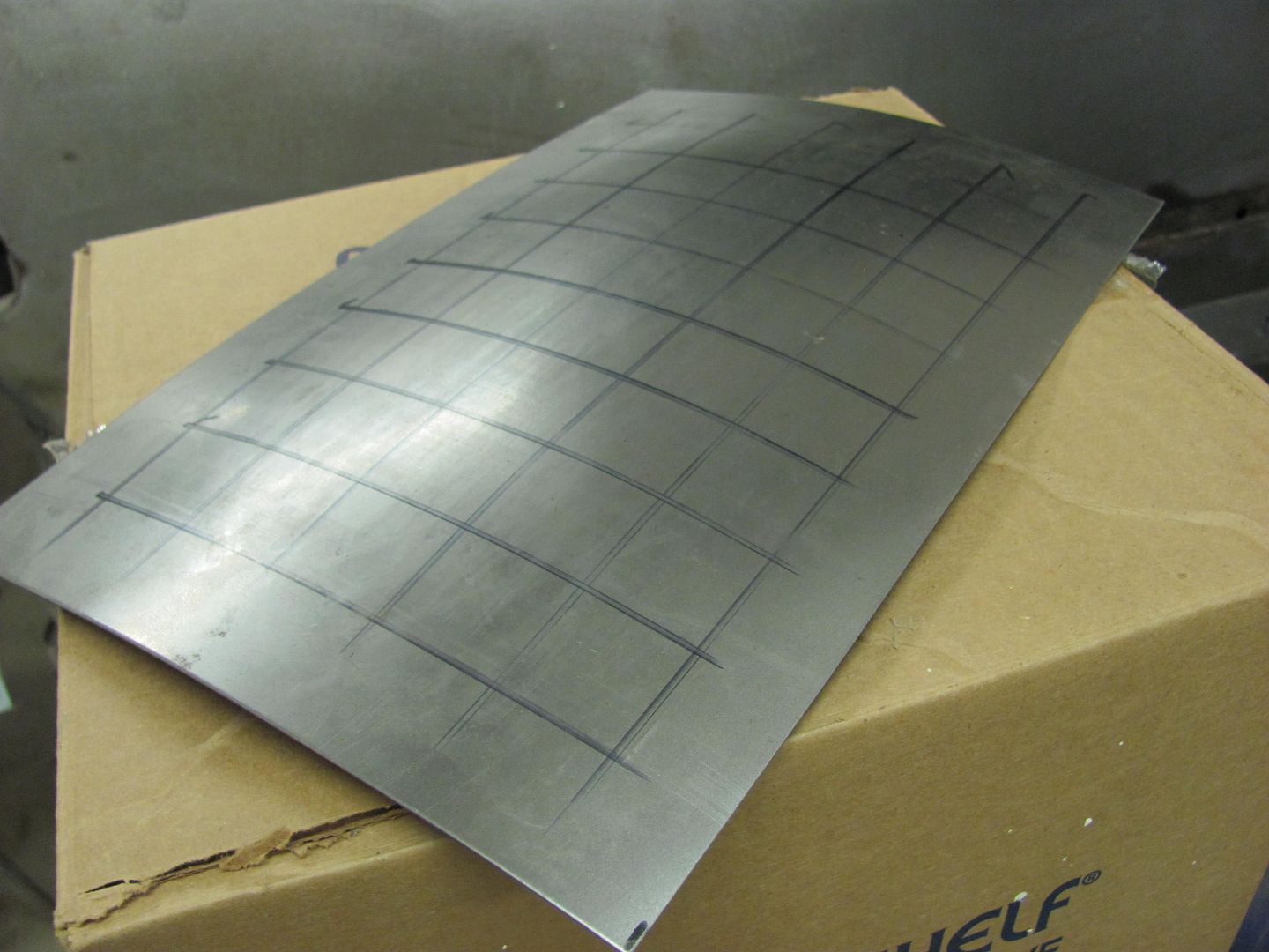
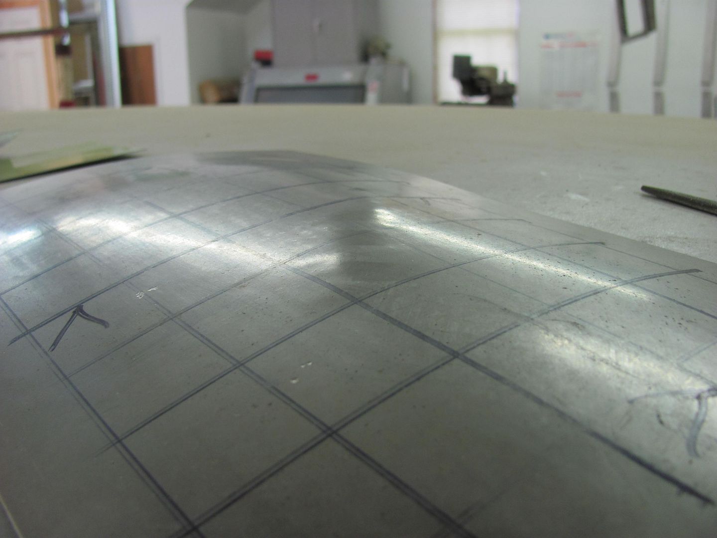
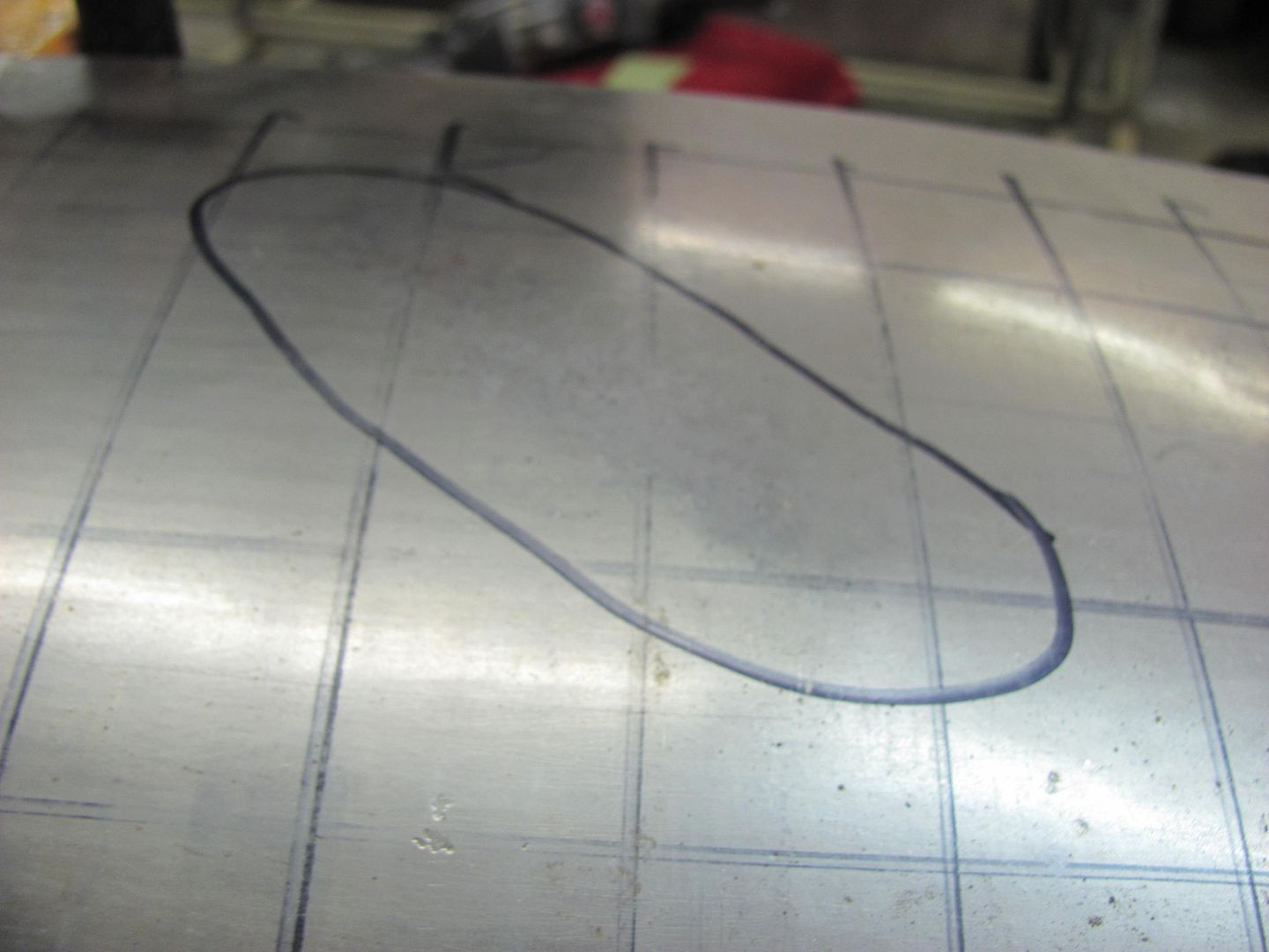
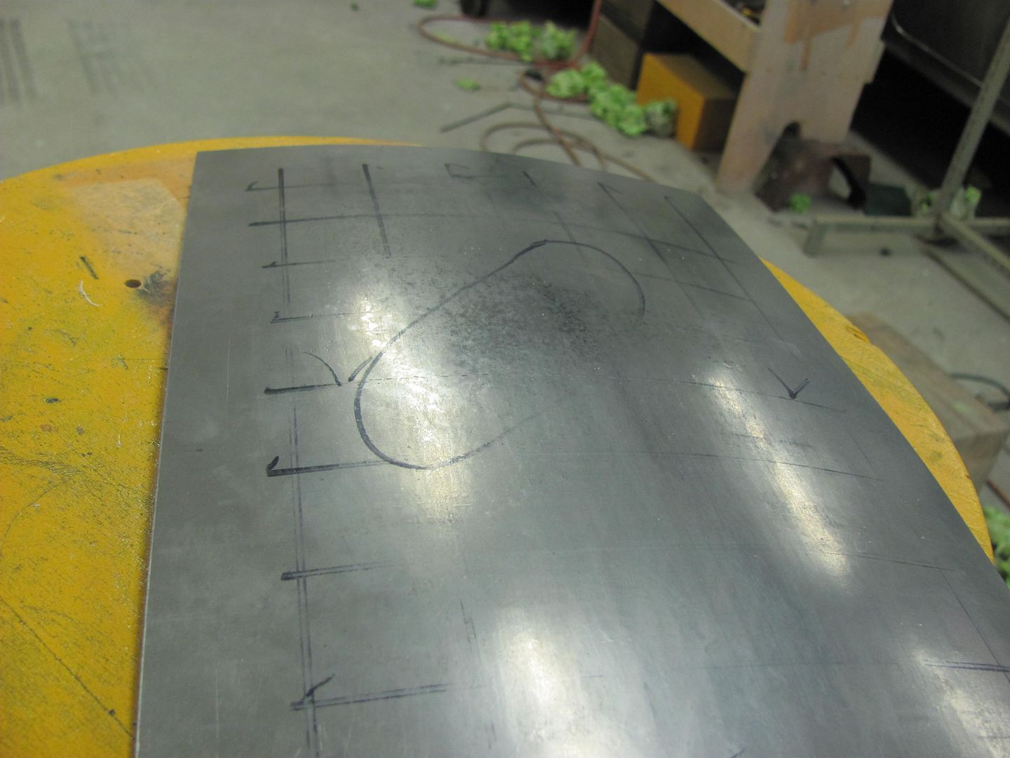
Grid layout for the Wheeling Machine, and completed "sample" roof...


Picture112.jpg


Picture113.jpg


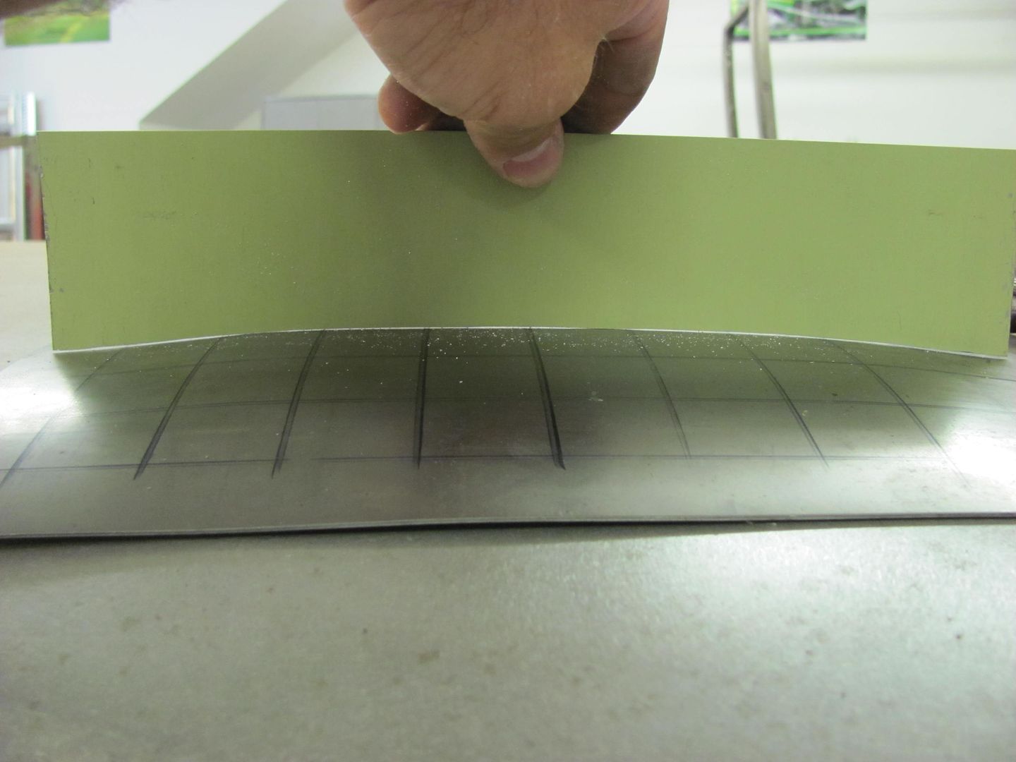
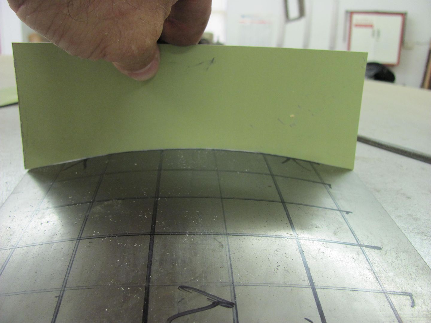
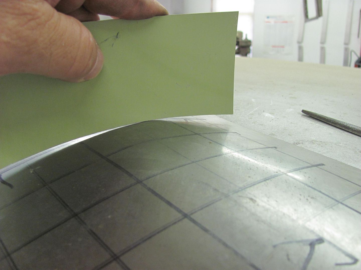
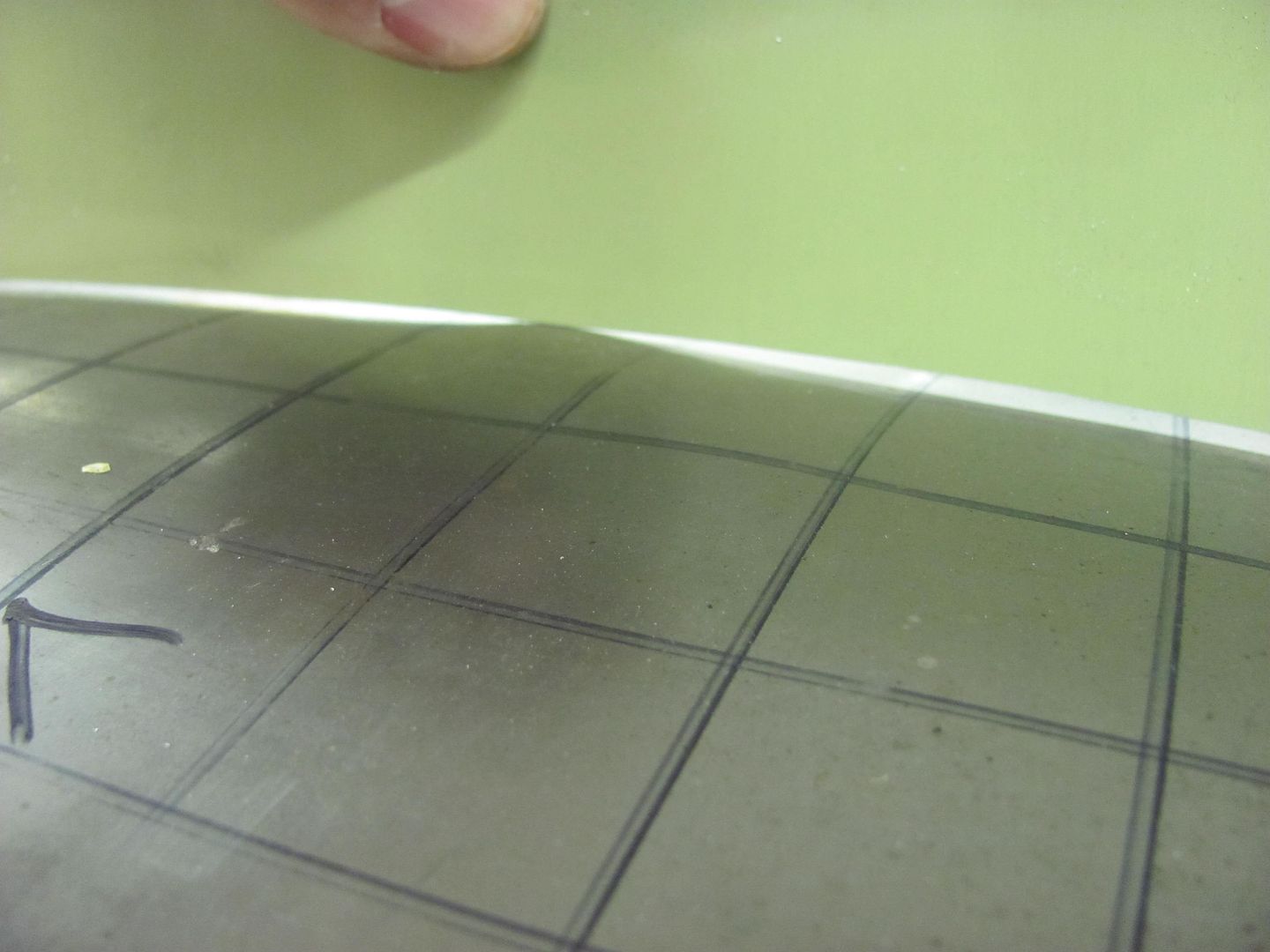
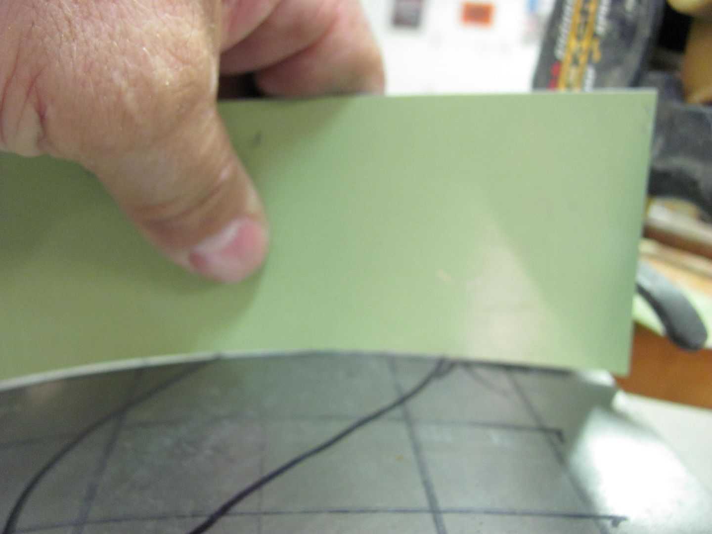
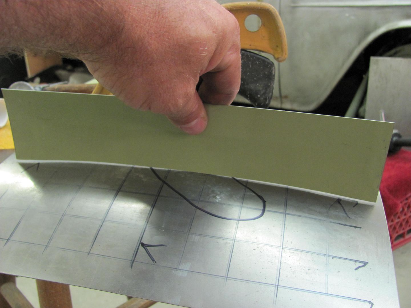
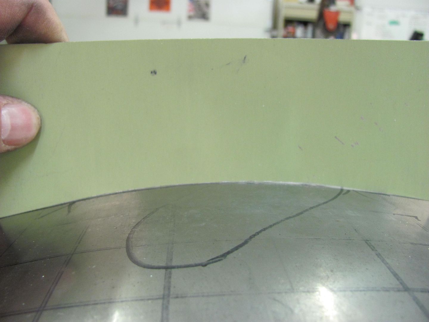
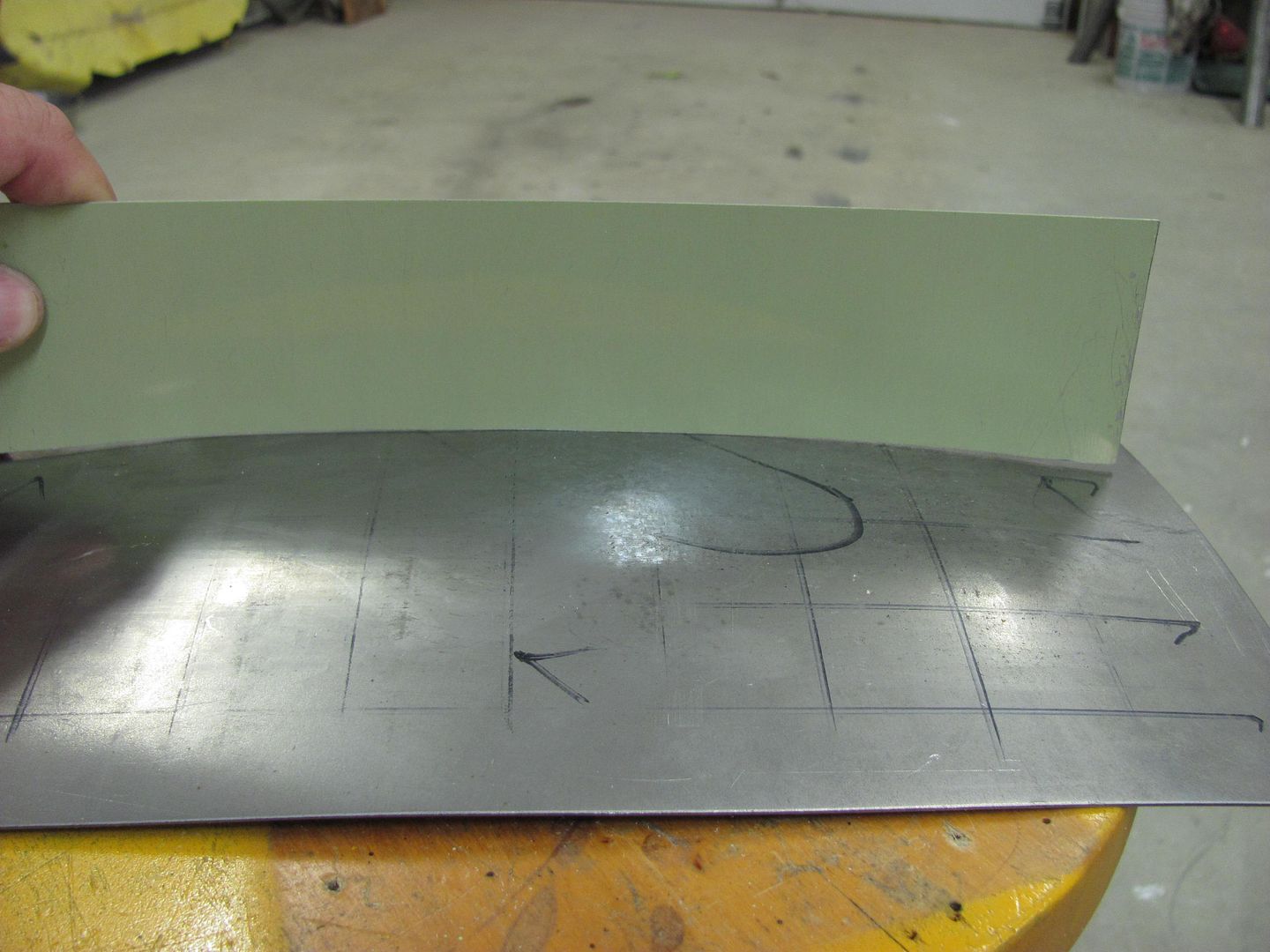
The first order of business should be to make some profile templates. In the case of an actual dented roof, use the opposite, undamaged side. This will allow you to check your progress as you go, and easily find the remaining high spots.


Picture114.jpg


Picture115.jpg


Using a crowned body hammer, a "dent" will be added from the back side, crossing both of our template areas.


Picture118.jpg


With the dent added:


Picture119.jpg


Picture120.jpg


Picture121.jpg


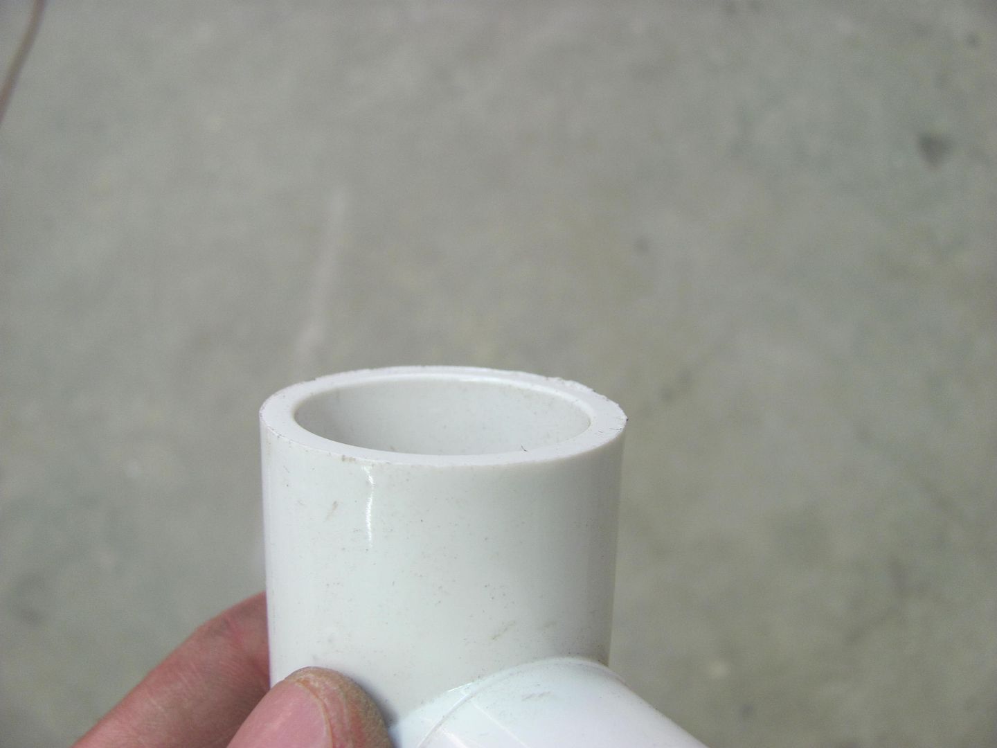
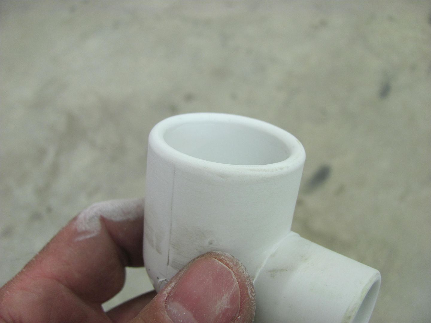
I chose to use a PVC elbow, it had two different sized ends for two tools in one. As with any body tool, they should be free of any burrs that may mar the metal surface. I also added a slight radius to the edges...


Picture123.jpg


Picture124-1.jpg


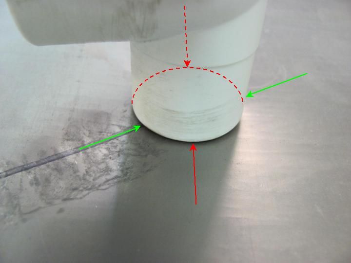
Holding the dolly against the bottom of the panel, you can see that due to the dents it only touches the panel at the red arrows. Based on off-dolly principle, the shrink would occur more prominently in the direction of the red arrows.


Picture142-1.jpg


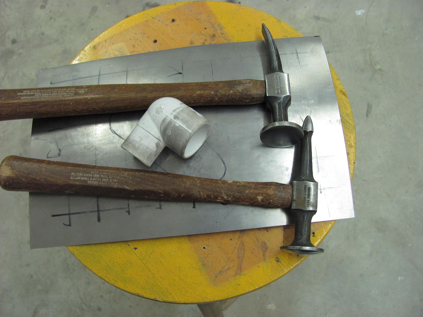
Here are the tools we will use today:


Picture140-1.jpg


After some off-dolly bumping:


Picture133-1.jpg


Check with the templates


Picture130-1.jpg


Picture131-1.jpg


Progress....these are light taps only with the hammer. We just want to bring down the high spots, not create craters.


Picture136-1.jpg


Picture137-1.jpg


Here's where I finished up...


Picture134-1.jpg


Picture135-1.jpg


I have a little over an hour in making the panel, denting, and removing the dent. Where I still could have gone a bit more, it was about to a point where high build primer should have masked any remaining imperfections. This dent removal could also have been accomplished with heat shrinking using an O/A torch, etc, but for those times where you may not wish to use heat and want another option, this seems to work well. I think with using the donut dolly and it's heftier mass, one could shave some additional time off the repair
 
Last edited:

e-tek

Well-known member
Joined
Dec 19, 2007
Messages
10,690
Location
Saskatoon, SK
Great stuff - I know a lot of guys will get something out of it. Funny thing is, I was just debating a lathe purchase and thought: "what would I actually use one for?". Thanks for the answer!


Side note - I was watching Search & Restore this morning and was amazed at the amount of "bondo" they used. They more than "skim-coated" the entire thing and had 10 guys sanding it down. I've done a LOT of cars and several have won show awards and never have I coated an entire car in filller.....:willy_nil Guess I'm not as 'experienced' as Tim Strange is.:dunno:
 
Last edited:

coronet

Member
Joined
Dec 24, 2009
Messages
8
You are one talented indvidual,I wish I had that skill set.Are you self taught?
 
OP
M

MP&C

Well-known member
Joined
Oct 21, 2009
Messages
4,389
Location
Leonardtown, MD
Trial and error, books, videos, and online resources. About the only "official" class I've taken has been a TIG class at the local community college. Did I mention trial and error? :lol_hitti
 
Last edited:
OP
M

MP&C

Well-known member
Joined
Oct 21, 2009
Messages
4,389
Location
Leonardtown, MD
Side note - I was watching Search & Restore this morning and was amazed at the amount of "bondo" they used. They more than "skim-coated" the entire thing and had 10 guys sanding it down. I've done a LOT of cars and several have won show awards and never have I coated an entire car in filller.....:willy_nil Guess I'm not as 'experienced' as Tim Strange is.:dunno:


As a possibility, perhaps the bondo manufacturer is a sponsor of the show :dunno:
I know my work isn't perfect, but I do try to get it to where a minimal amount of Evercoat 416 or high build will address any issues.
 
OP
M

MP&C

Well-known member
Joined
Oct 21, 2009
Messages
4,389
Location
Leonardtown, MD
Got a new purchase in the mail today, it came with what appears to be the original handle. Can't make out the writing on it, but I can see it there. It is a bit loose, so the new hickory S-O is slated for install once the hammer faces are polished up...


Picture167-2.jpg


Picture167-2.jpg


Picture168-2.jpg


Picture169-2.jpg


Picture170-2.jpg


Also got started on wet sanding the Starliner valve covers....


Picture171-1.jpg


Picture172-3.jpg


....pay no attention to the flying pig...
 
OP
M

MP&C

Well-known member
Joined
Oct 21, 2009
Messages
4,389
Location
Leonardtown, MD
Mother-in-law's yard art. She asked if I had a sandblast cabinet, told her to come over and I'd show her how to use it. I think she was under the impression it was automated. She dropped the pig off and left. I haven't had time for any "automation", so I think I may pick up some POR, it looks like a good candidate for it as is..
 
OP
M

MP&C

Well-known member
Joined
Oct 21, 2009
Messages
4,389
Location
Leonardtown, MD
Worked on cleaning up my "new" hammer this evening. Here it is right out of the box....


Picture167-2.jpg


Note this face is a bit on the pitted side...


Picture169-2.jpg


The handle was loose, and I did have some extras in the tool box, so we'll clean up the hammer faces first and then install the new hickory handle...


Picture170-2.jpg


I used the DA and foam interface pad on the faces to keep from sanding in flat spots. The interface pad helps to conform to the surface, as seen here.....


Picture080.jpg


Started with 320 grit and worked up to 3000 trizact


Picture176-3.jpg


Picture177-2.jpg


And with the new handle...


Picture179-2.jpg


Picture180-3.jpg


Picture181-3.jpg
 
To avoid these ads, REGISTER NOW!
Top Bottom